 IQDuino
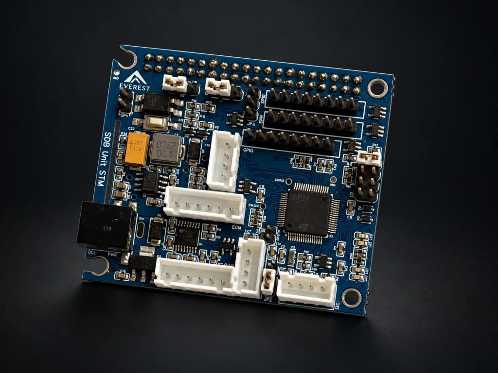
Port counts
| Peripheral UART | 4 interfaces: EGM/UART1, RS/UART2, UART3, VUART4. VUART4 depends on firmware implementation. |
|---|---|
| RS-232 | 2 channels on EGM and RS/UART2, shared with the corresponding UARTs; not extra independent channels. |
| SBC UART link | 1 MCU UART0 channel switched between two SBC UART pairs by JP2/JP3. |
| SPI | 2 peripheral connectors, SPI0 and SPI1, routed from the SBC. MCU ICSP signals are counted separately as programming. |
| I²C | 1 connector, 1 SDA/SCL bus; multiple devices require compatible addresses and levels. |
| GPIO | 1 connector: 6 signal lines plus power and ground. |
| Optocoupler output | 1 optocoupler transistor output on JP1. |
| Configuration and indication | 4 configuration pairs, 1 button, 4 controllable LEDs and 1 power indicator. |
Platform overview
A ready-made peripheral interface platform for single-board computers. UART, two RS-232 channels, SPI, I²C and GPIO connect project software to external devices without designing a separate interface board.
The board includes four LEDs, configuration jumpers/DIP switches, a button and an optocoupler. Arduino toolchain compatibility supports custom firmware for peripheral communication and single-board computer integration.
Controller variants
| IQDuino ST128 | STM32F103RBT6 · 128 KB Flash |
|---|---|
| IQDuino ST256 | STM32F103RCT6 · 256 KB Flash |
| IQDuino ST384 | STM32F103RDT6 · 384 KB Flash |
| IQDuino ST512 | STM32F103RET6 · 512 KB Flash |
Key specifications
| Microcontroller | STM32F103RB / RC / RD / RE |
|---|---|
| Device interfaces | UART / 2 × RS-232 / I²C / SPI / GPIO |
Power for the complete assembly
Input: 12 V. The integrated converter provides 5 V / 3 A, up to 15 W shared by the controller, single-board computer, display and peripherals. A 3.3 V peripheral supply is also available. Total consumption and startup currents must fit the assembly power budget.
Development and updates
Programming options include SWD, bootloader pins and updates through the single-board computer. The procedure depends on the bootloader and project configuration, allowing an integrated device to be maintained without removing its controller.
Peripheral integration
Connect banknote acceptors, banknote dispensers, receipt printers, readers, sensors and actuators through their supported interfaces and protocols. The SBC handles the user interface, network and database; IQDuino handles hardware communication, enabling terminals without a separate desktop PC.
Single-board computer assemblies
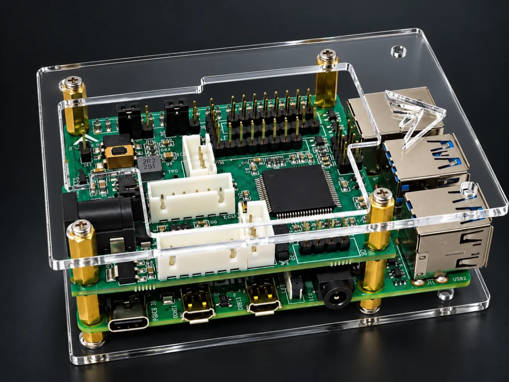
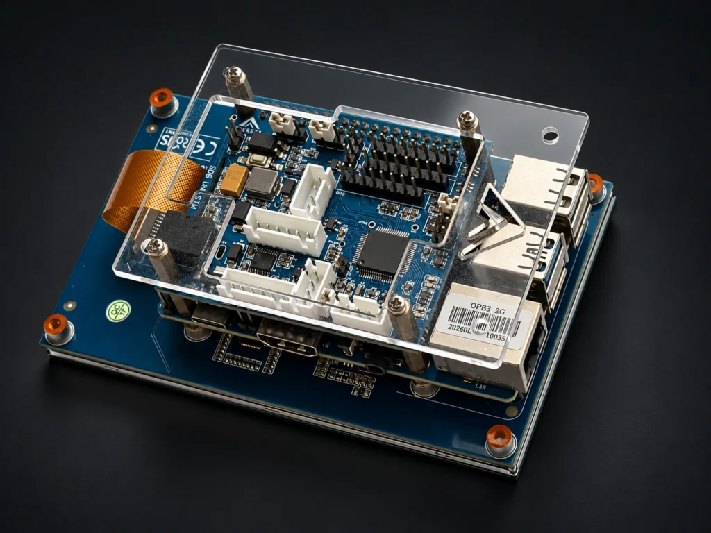
Configurations include a single-board computer, protective enclosure, display or display-free assembly. Platform families for configuration selection include Raspberry Pi 3/4/5, Orange Pi, ROCK Pi 4A/4B, Repka Pi and ASUS Tinker Board 1/2. The SBC model, mechanics, pin mapping and power budget are checked for each assembly.
IQDuino ST connector pinout
Connector functions below are derived from the supplied schematic. Check pin 1 orientation against the markings of the actual revision. Circuit schematics are not published.
| I²C · 1 / 2 / 3 / 4 | SDA / SCL / GND / +5 V |
|---|---|
| UART3 · 1 / 2 / 3 / 4 | GND / TX3 / RX3 / VUART3 |
| GPIO · 1 / 2 / 3 / 4 | +5 V / GPIO2 / GND / GPIO4 |
| GPIO · 5 / 6 / 7 / 8 | GPIO5 / GPIO6 / GPIO7 / GPIO8 |
| SWD | SWDIO / SWCLK / GND |
The manufacturer reports several years of continuous 24/7 operation for the controllers and readers.
Choose a configuration
Tell us the processor, interfaces, cards, mounting format and SBC model you need. We will prepare a configuration for your project.
Controller form factors
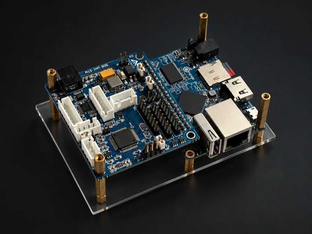
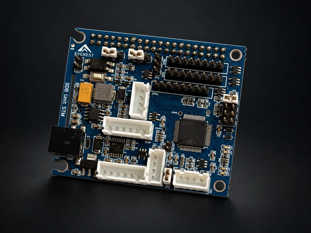
- OEM — board only
- Enclosure for single-board computer integration
- Dedicated Orange Pi One enclosure
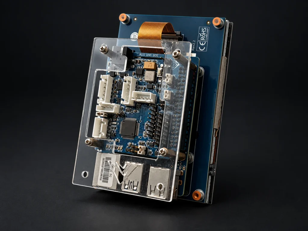
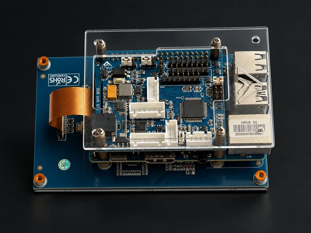
- Monitor-mount enclosure with single-board computer
Raspberry Pi 3/4/5, ROCK Pi 4A/4B, Orange Pi PC/PC2/3B and ASUS Tinker Board 1/2. Mounting and interface configuration are selected for the particular assembly.
Photos and configurations
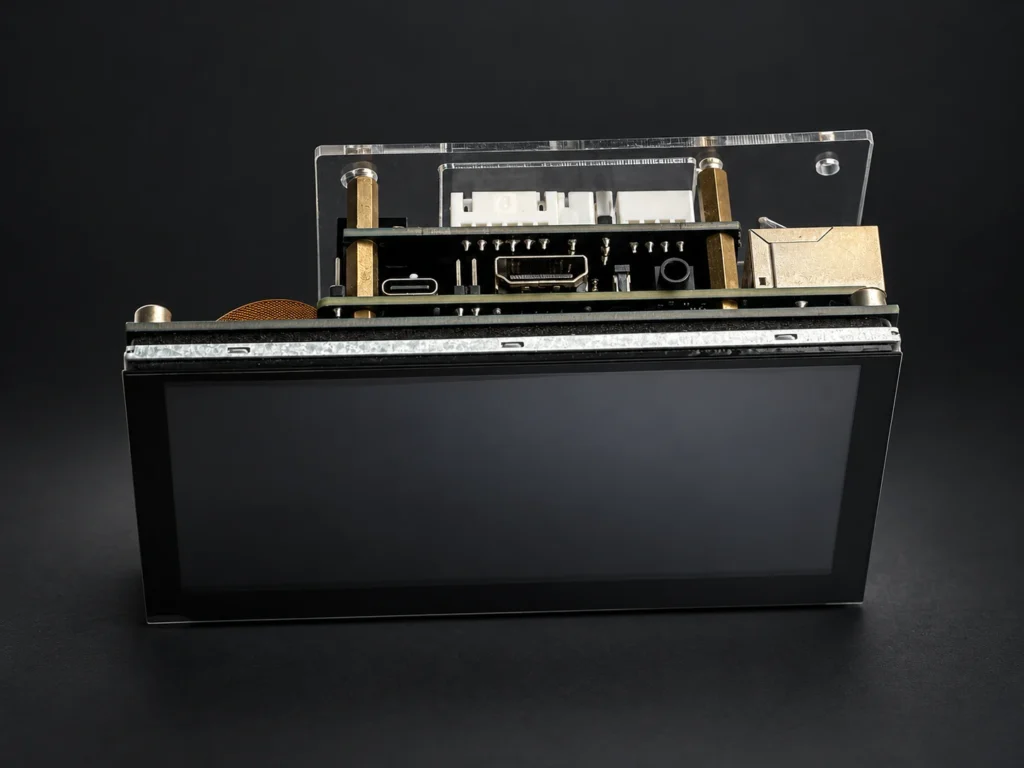
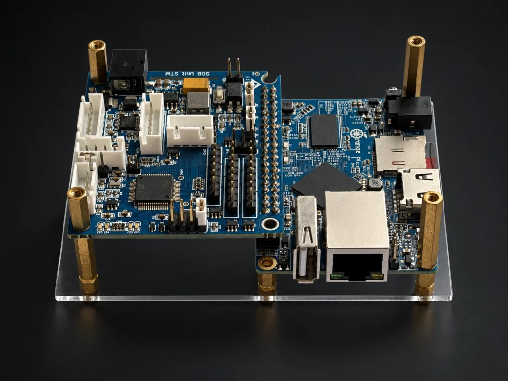
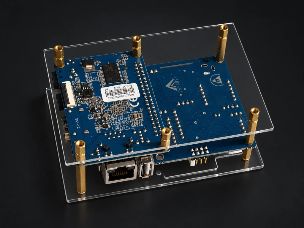
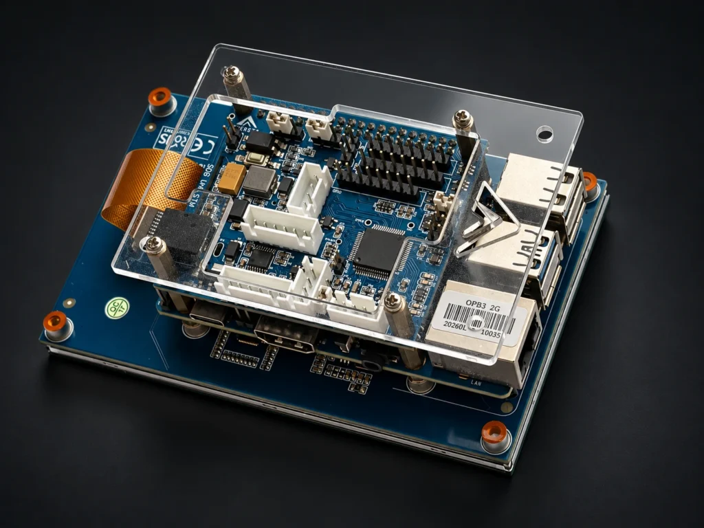
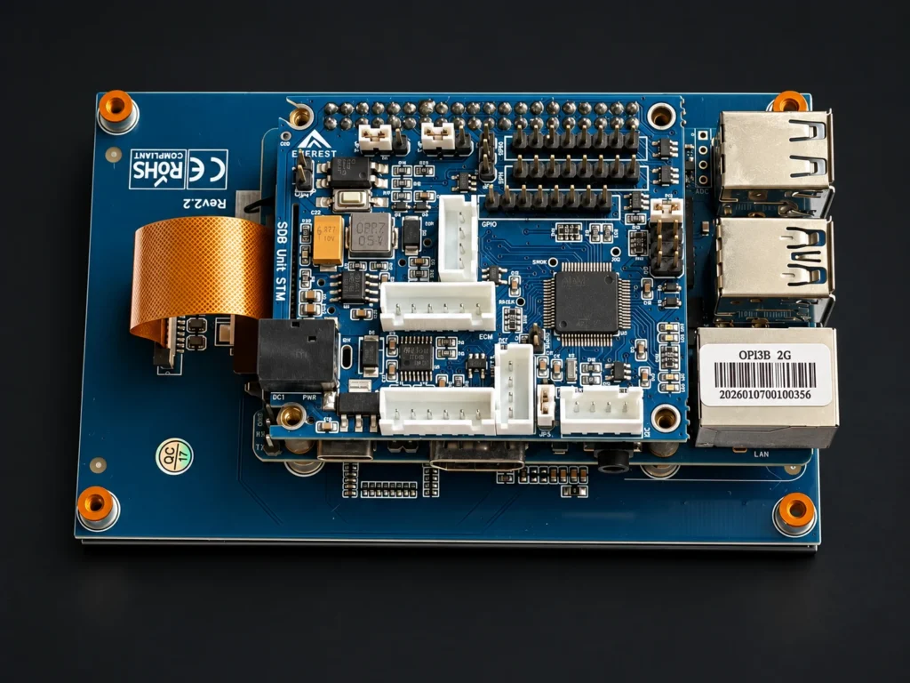
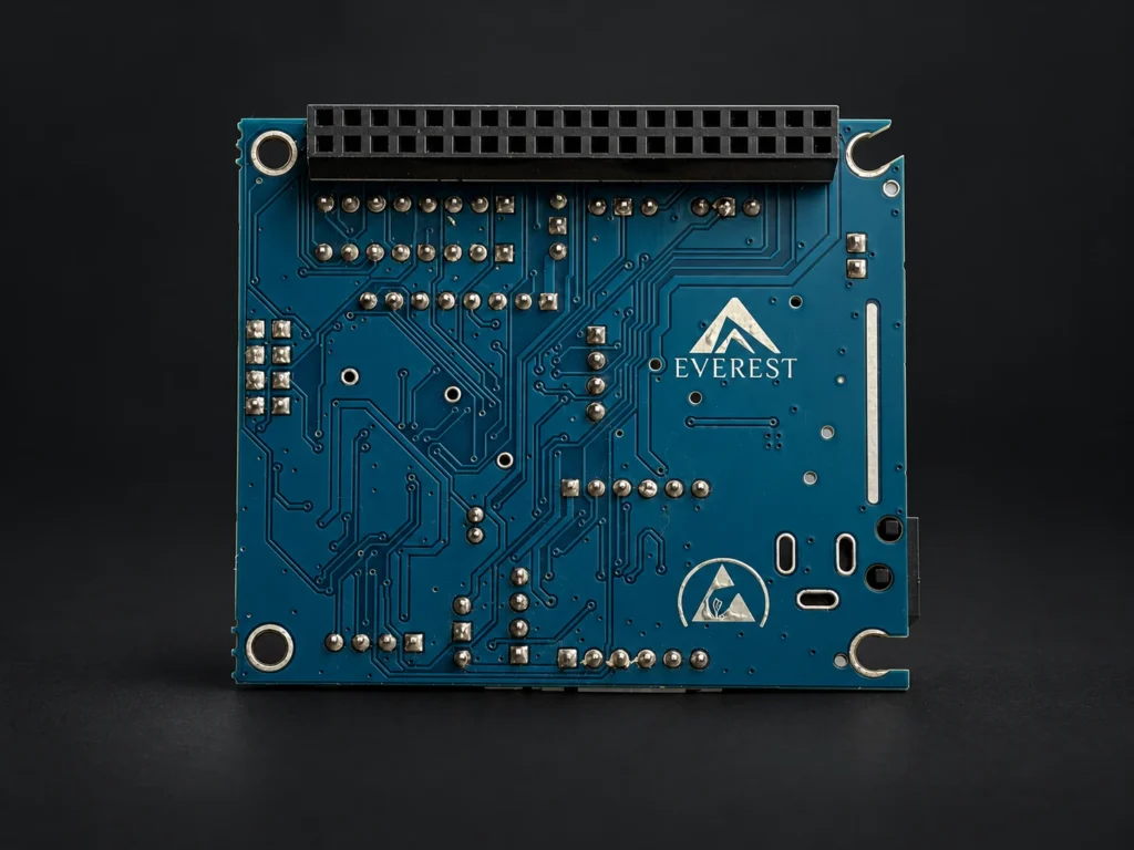
Ports and connections
Pin numbers follow connector symbols in the schematics dated 2026-10-28. Check pin 1 and cable orientation against the PCB revision. TX/RX are relative to the board.
| EGM | 1 RS-232 TX1; 2 RS-232 RX1; 3 GND; 4 UART TX1; 5 UART RX1; 6 +5 V |
|---|---|
| RS/UART2 | 1 RS-232 TX2; 2 RS-232 RX2; 3 GND; 4 UART TX2; 5 UART RX2; 6 +5 V |
| UART3 | 1 GND; 2 TX3; 3 RX3; 4 VUART3 (JP5: 3.3/5 V) |
| VUART4 — STM32 | 1 GND; 2 VUART4/TX (VRX4); 3 VUART4/RX (VTX4); 4 +5 V |
| I²C | 1 SDA; 2 SCL; 3 GND; 4 +5 V |
| SPI0 — STM32 | 1 VSPI0 (JP4: 3.3/5 V); 2 SPI0 RTS; 3 GND; 4 NC; 5 MISO; 6 MOSI; 7 SCLK; 8 CS0 |
| SPI1 | 1 +5 V; 2 SPI1 RST; 3 GND; 4 ICSPNSS (STM32) / SPI1 IRQ (AVR); 5 MISO; 6 MOSI; 7 SCLK; 8 CS0 |
| GPIO | 1 +5 V; 2 GPIO2; 3 GND; 4 GPIO4; 5 GPIO5; 6 GPIO6; 7 GPIO7; 8 GPIO8 |
EGM and RS/UART2 each expose one serial channel as RS-232 and logic-level UART: two channels, not four independent ports. UART3 and VUART4 use logic levels, not RS-232. GPIO provides six signal lines plus power and ground.
Connecting a single-board computer
With power off, fit the verified adapter for your SBC. JP2/JP3 select one of two SBC UART pairs: common pin 2 connects to 1 or 3. Connect TX to the other side’s RX and share ground. Enable the UART in the OS, release it from the serial console and match settings to the controller firmware. Linux device names and overlays depend on the SBC.
SPI0/SPI1 route from the SBC connector. JP4 selects SPI0 power and JP5 selects UART3 power: 3.3 or 5 V. These jumpers do not translate signal levels. I²C pull-ups connect to MCU power; a 5 V AVR configuration requires level matching to 3.3 V GPIO. VUART4 and auxiliary SPI signals differ between STM32 and AVR: use the correct version’s pinout.
12 V input; shared 5 V / 3 A / 15 W budget for controller, SBC, display and peripherals. 3.3 V peripheral power is available; its current limit depends on the assembly. Prevent backfeeding when using multiple power sources.
The OPI1 schematic symbol uses adapted numbering. Do not transfer its numbers directly to a Raspberry Pi, Orange Pi or another SBC GPIO header. Use a verified adapter for the specific assembly and PCB revision.
STM32 programming: SWDIO PA13, SWCLK PA14, GND and a 3.3 V reference. BOOT/RESET routing depends on the adapter revision. Connector UART names are board net names; hardware/software UART availability depends on firmware and MCU.